HiSpeed Reveal
General
Installation Manual
Installation Manual

No part of this publication may be duplicated or edited in any form or by any means, including any type of electronic or mechanical method without prior written permission from ShowTex.
ShowTex and its employees are fully aware of their task to provide a reliable edition of this document. Nevertheless, they cannot accept any form of liability for the direct or indirect consequences of imperfections that might remain in this edition. The material in this manual is subject to change without notice.
ShowTex warrants that its mechanical and technical products, when delivered in new condition, in original packing, sold directly and used in normal conditions are free from any defects in manufacturing, materials and workmanship. For more information about your local warranty terms, please check our website or contact your local ShowTex office.
All products from the ShowTex Rental range are supposed to be returned in the same state as they were rented. Please treat our products with care, allowing the next user to enjoy the products as much as you did. The rented products are internally checked according to the general rental conditions. Be sure to check our rental guidelines on our website before installing and using this product: ShowTex rental guidelines
Read and understand this user manual before installing and or operating the system. Failure to follow the instructions in this document could result in serious injury!
Following the guidelines of this manual will reduce the risk of damaging the equipment or injuring yourself and the people around you. Nevertheless, ShowTex cannot be held accountable for any use or misuse of the equipment and supplies.
Damage to the system caused by any other method of installation than the one shown in this manual can only be repaired or fixed at the customer’s expense.
As a result of the above warning, any ShowTex product must be installed and operated by a qualified technician who knows its capabilities as well as its limitations.
In case you are uncertain about the eligibility of any hardware in your product, please get in touch with your local ShowTex office to receive additional guidance.
Thank you for choosing for ShowTex and purchasing one of our products. We want to ensure that your experience is as smooth and safe as possible, so we kindly request that you take a few moments to carefully read this manual before installing your new system.
This manual contains important information that will help you comply with health and safety regulations, as well as provide guidance on how to safely install, operate and maintain your product. Our team has taken great care to ensure that this manual is easy to understand and follow, using straightforward language and clear illustrations.
If you have any questions or concerns regarding the installation or use of your product, please feel free to contact your local ShowTex office. Our knowledgeable team members are always available to assist you and answer any questions you may have.
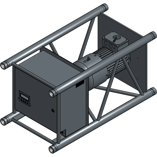
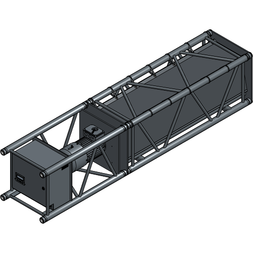
| Article number | Colour | Weight |
|---|---|---|
| 8140 3117 0087 | Black | 74.00 kg |
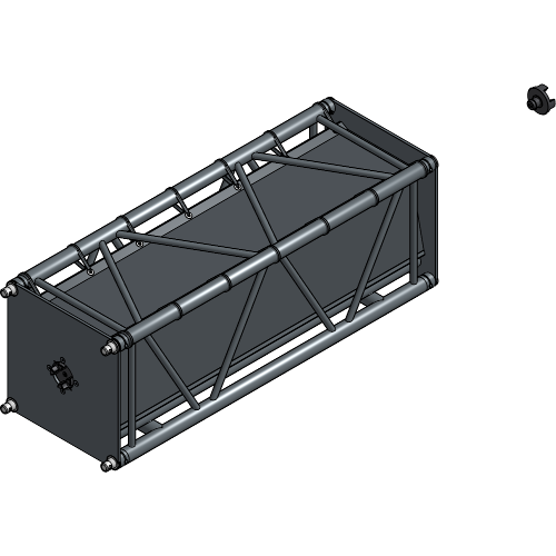
| Article number | Colour | Length | Weight |
|---|---|---|---|
| 8140 3117 0097 | Black | 1.50 m | 40.00 kg |
| 8140 3117 0107 | Black | 3.00 m | 60.00 kg |
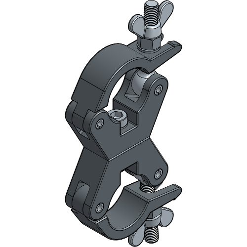
| Article number | Colour | ⌀ | WLL | SF | Weight |
|---|---|---|---|---|---|
| 8700 0683 7507 | Black | 48-51 mm | 750.00 kg | 5:1 | 0.86 kg |
| 8700 0683 7504 | Galvanised | 48-51 mm | 750.00 kg | 5:1 | 0.86 kg |
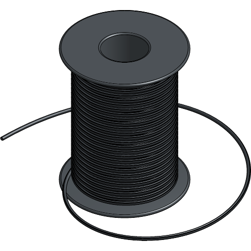
| Article number | Colour | Length | ⌀ | WLL | SF | Weight |
|---|---|---|---|---|---|---|
| 7550 0002 0007 | Black | 100.00 m | 2 mm | 12.00 kg | 10:1 | 0.38 kg |
| 7550 0002 0003 | White | 100.00 m | 2 mm | 12.00 kg | 10:1 | 0.38 kg |
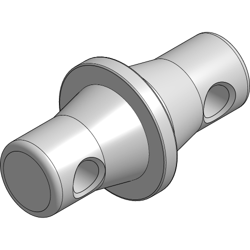
| Article number | Colour | Weight |
|---|---|---|
| 8140 2247 0124 | Aluminium | 0.18 kg |
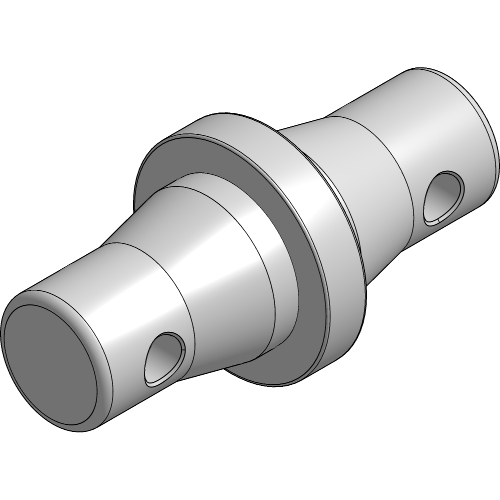
| Article number | Colour | Weight |
|---|---|---|
| 8140 2247 0224 | Aluminium | 0.23 kg |
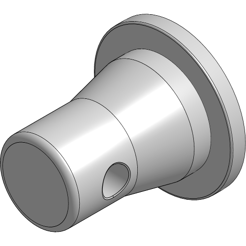
| Article number | Colour | Weight |
|---|---|---|
| 8140 2247 0004 | Aluminium | 0.11 kg |
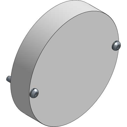
| Article number | Colour | Weight |
|---|---|---|
| 8140 3116 3027 | Aluminium | 0.50 kg |
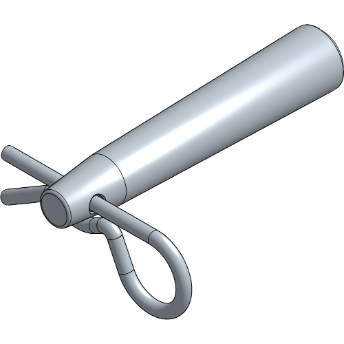
| Article number | Colour | Weight |
|---|---|---|
| 8140 2247 0014 | Aluminium | 0.04 kg |
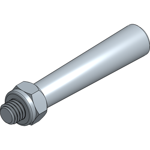
| Article number | Colour | Weight |
|---|---|---|
| 8140 2253 0001 | Aluminium | 0.05 kg |

| Article number | Colour | Weight |
|---|---|---|
| 8140 9999 0007 | Red | 0.05 kg |
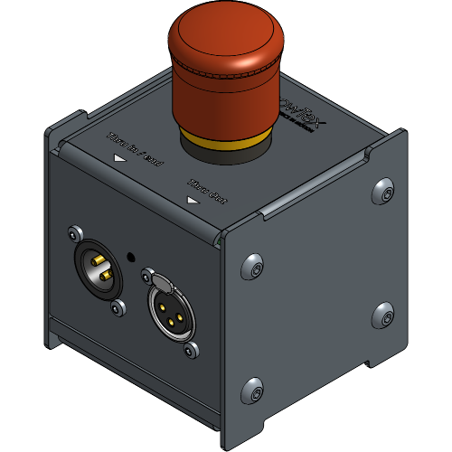
| Article number | Colour | Weight |
|---|---|---|
| 8140 3117 0037 | Black | 0.75 kg |
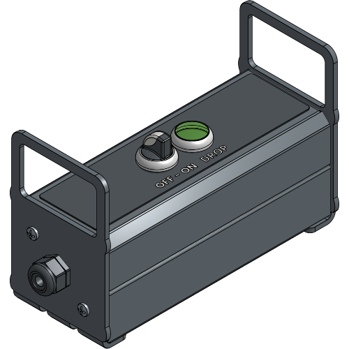
| Article number | Colour | Weight |
|---|---|---|
| 8150 0950 0010 | Black | 5.75 kg |
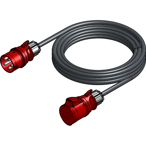
| Article number | Cable | Length | Weight |
|---|---|---|---|
| 8140 3117 0017 | CEE32A / 380V | 10.00 m | 6.00 kg |
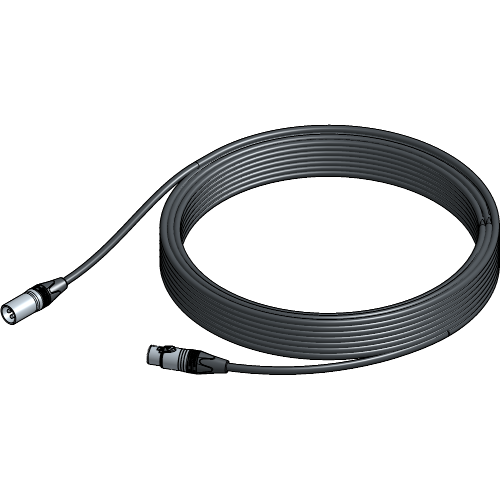
| Article number | Cable | Length | Weight |
|---|---|---|---|
| 8140 3117 0047 | XLR 3 | 25.00 m | 1.20 kg |
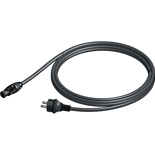
| Article number | Cable | Length | Weight |
|---|---|---|---|
| 8145 0912 0017 | True1 / Schuko | 2.00 m | 0.78 kg |
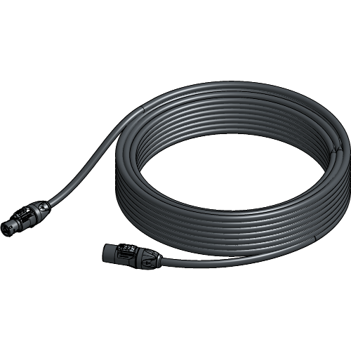
| Article number | Cable | Length | Weight |
|---|---|---|---|
| 8140 3117 0027 | True1 M/F | 25.00 m | 3.28 kg |
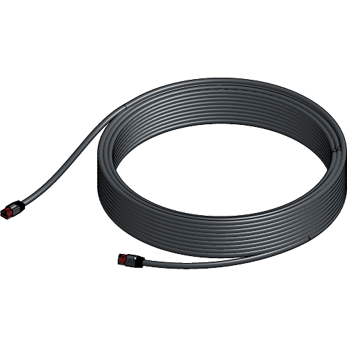
| Article number | Cable | Length | Weight |
|---|---|---|---|
| 8140 3117 0227 | Cat 6 | 30.00 m | 0.88 kg |
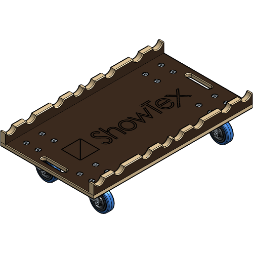
| Article number | Colour | Weight |
|---|---|---|
| 8140 6050 0407 | Brown | 15.20 kg |
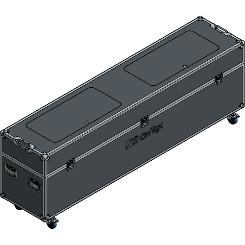
| Article number | Colour | Weight |
|---|---|---|
| 8140 6050 0507 | Black | 110.00 kg |
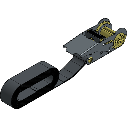
| Article number | Colour | Length | Weight |
|---|---|---|---|
| 8800 0372 3007 | Black | 3.00 m | 0.27 kg |
| 8800 0372 5009 | Black | 5.00 m | 0.32 kg |
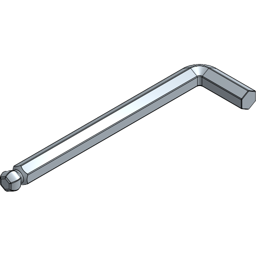
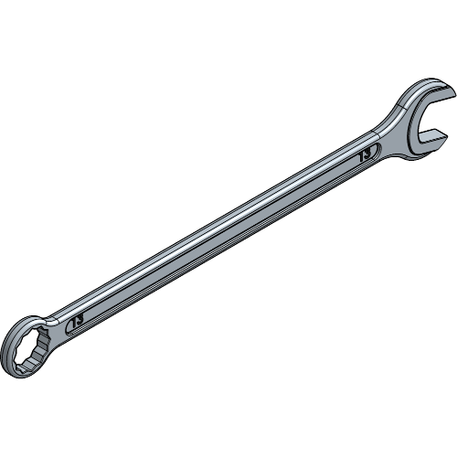
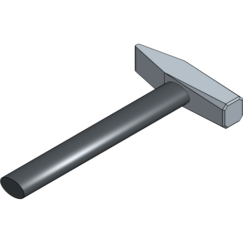
If the HiSpeed setup was delivered assembled, proceed to chapter: Rigging the HiSpeed Reveal.
Place the Coupling Spider on the coupling jaw of the motor.
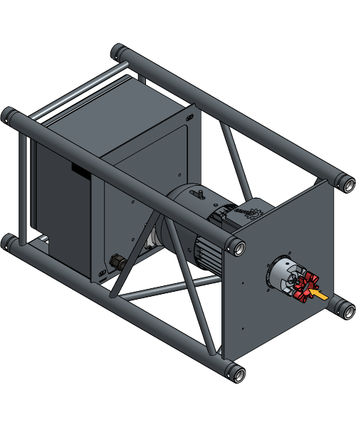
Align the coupling jaw of the Truss Roller with the coupling jaw of the motor, and insert the Conical Couplers of the Truss Roller into the Motor Truss.
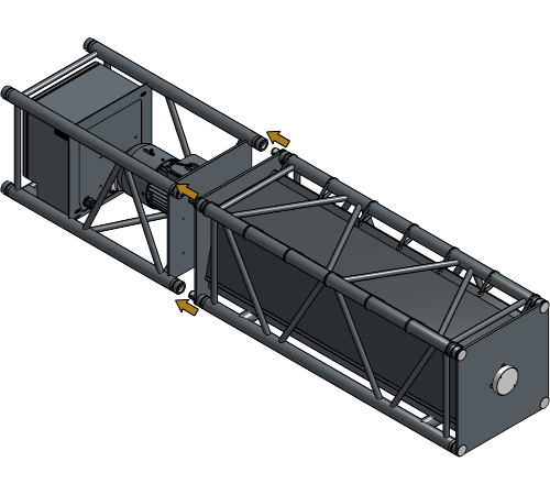
Ensure that the coupling jaw of the motor and the Truss Roller are aligned. If they are not aligned, rotate the Truss Roller until they fit.
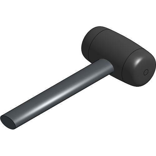
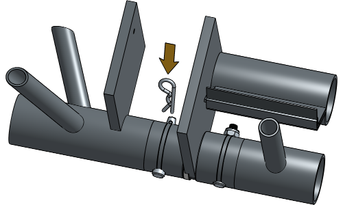
Insert a Pin into each of the four holes in the motor, and hammer the Pins in to secure all Conical Couplers.
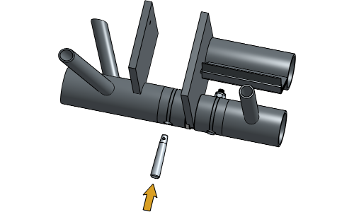
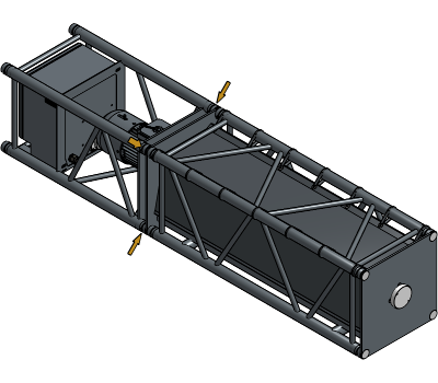
Insert a Safety Clip in all four holes of the Pins.

For extra information and details about the electrical wiring and connectors, refer to the Technical Data Sheet of the HiSpeed Reveal.
Plug the Power Supply Extension Cable into the motor.

Plug the Emergency Stop Cable into both the Emergency Stop and the motor. The Emergency Stop Cable can be extended with additional Emergency Stop Cables if required.
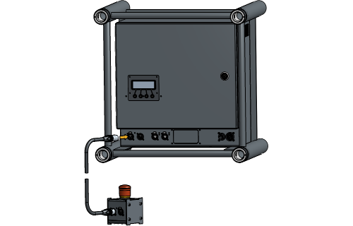

The Emergency stop has a blue LED that lights up when it is connected and working. If he blue LED is not on, the Emergency Stop hasn’t been properly connected or is engaged. Disengage the Emergency Stop or check if all plugs are fully secured and connected.
Connect any additional Emergency Stops to the first Emergency stop as needed.


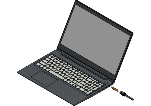
Plug the Network Cable into the motor and a laptop.

Plug the Power Supply Cable into the motor. The Power Supply Cable can be extended with Power Extension Cables if required.
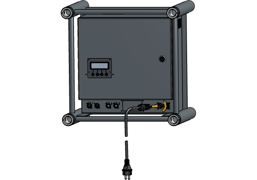
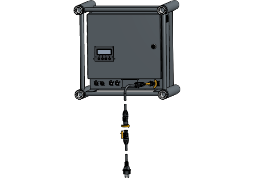
Plug the Power Supply Cable into the Remote.
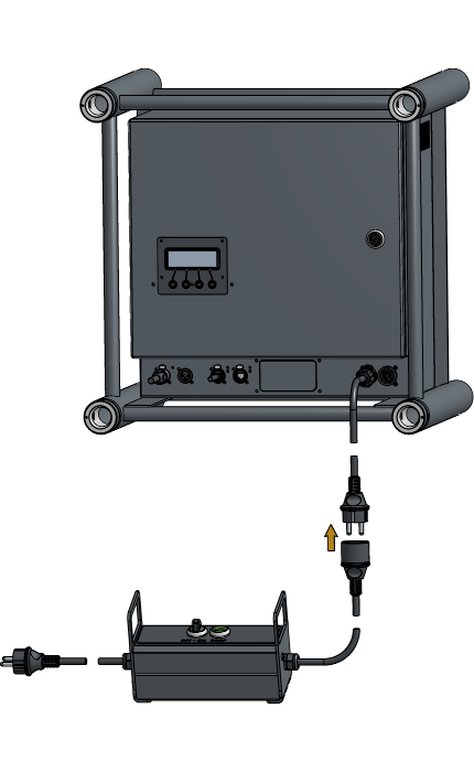
Ensure that all plugs are in their locked position. Ulocked cables may result in poor contact or no contact. If any plugs are not locked, insert the plug fully and twist to secure it.
Cables without a locking function should be securely taped to prevent poor contact or disconnection when the HiSpeed Reveal is hoised onto the truss.
Provide the rigging points that are required for your setup on the HiSpeed Reveal and the truss.
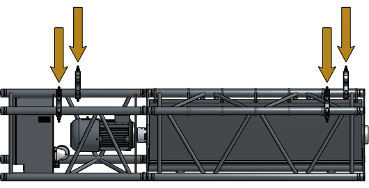
The nuts and wingnuts of the Turn Couplers should be fully tightened before hoisting.
Hoist the HiSpeed Reveal to eye level for easy access.
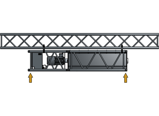
For more information about the correct rigging points for each setup, refer to the Technical Data Sheet.
When using 1 Flange in your setup, position it in the center while placing the unused Flange to the side.
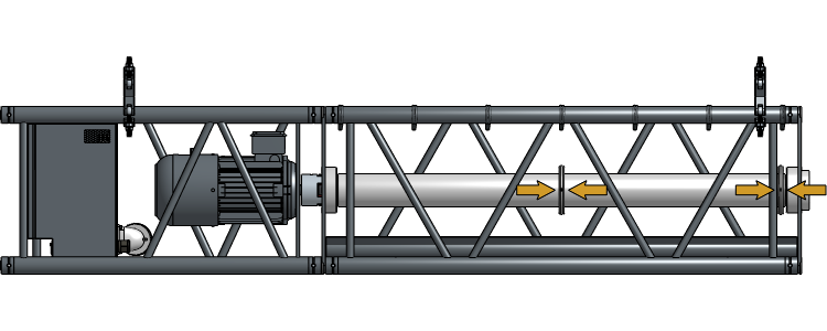
When using 2 Flanges in your setup, position both of them at 1/3 of the Roller width. Each Flange uses a different RibCord.

Loosen the set screws of the Flanges and move them to the desired position according to your setup.
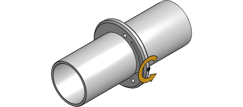

Tighten the set screws once the Flanges are correctly positioned. When using 2 Flanges, make sure they are properly aligned.


Insert the RibCord into the Flange.

Tie a bowline knot to secure the RibCord to the Flange.

To observe the RibCord’s rolling direction, navigate to
Reference move. Press the
✔ key to enter the menu and hold the
▲ key to execute a reference move with the
roller.
The status should display STS: Ready.
If not, check whether the Emergency Stop Unit has been disengaged.
The RibCord should roll up towards the backside of the axle. If
not, navigate to
Config > Motion > Invert motion. Use
the + key to select “On” and validate with
the ✔ key.
Navigate back to Reference move.
Press and hold the ▲ key to ensure the
RibCord now rolls up towards the backside of the axle.
For safety reasons, the RibCord should have 5 safety turns on the
roller. Navigate to Reference move, press
and hold the ▲ key to activate the roller
and perform at least 5 turns.
The HiSpeed Reveal is now completely prepared to hoist it to the correct location for the reveal.
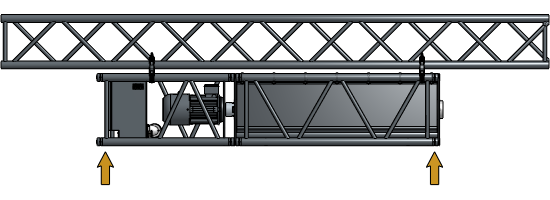
Make sure the HiSpeed Reveal remains accessible for testing by providing an elevator or platform.
Navigate to Reference move. Press
and hold the ▲ key to roll up the RibCord
to the required length based on your setup.
Mark the RibCord with a piece of tape where it meets the bottom of the Truss.

Your HiSpeed Reveal is now completely installed and ready to configure!
Periodic, regularly scheduled maintenance inspections are necessary as the HiSpeed Reveal has components that must be inspected, adjusted, maintained and replaced. To ensure the safety and proper functioning of the system, it is essential to establish a routine inspection.
Please follow the provided schedule below as the minimum maintenance program. After the operating personnel gains experience with the system within the initial year, additional measures and adjustments may be implemented based on your systems specific needs.
| Every week | Every 6 months | |
|---|---|---|
| Operate the HiSpeed Reveal. | X | |
| Inspect if HiSpeed Roveal system is operating smoothly. | X | |
| Check if the latest version of the UMC software is installed. | X | |
| Listen for unusual noise at level of the bearings of the Truss Roller. | X | |
| Listen for unusual noise at level of the motor. | X | |
| Inspect whether all Pins with safety Nuts or Safety Clips are securely in place. | X | |
| Inspect whether all rigging points are secure. | X | |
| Inspect the condition of the Turn Couplers, nuts and wingnuts. | X | |
| Inspect the condition of the Flanges and setscrews. | X | |
| Inspect the condition of the bag, RibCord, curtain and attachment points. | X | |
| Inspect whether the marking on the RibCord remains intact. | X | |
| Inspect whether the HiSpeed Reveal remains properly rigged and level. | X | |
| Inspect whether all cables, emergency stops and remote are plugged in correctly. | X | |
| Inspect whether the curtain makes unnecessary movements before entering the bag. | X | |
| Inspect whether the curtain makes unnecessary rotations and movements in the bag during the reveal. | X |
Within 24 hours of using a recently installed HiSpeed Reveal System, perform all of the maintenance steps above.
Instances of above-average use or operating the curtain in surroundings with high humidity, dust or extreme temperature changes may require shorter intervals than indicated in the Care & Maintenance.
For more technical assistance, please contact your local ShowTex
office.
The address and contact information can be found on our website:
www.showtex.com