5.1 Main Interface
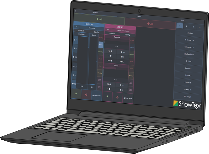
The main sections of the control interface are shown in the following image:

Installation Manual
No part of this publication may be duplicated or edited in any form or by any means, including any type of electronic or mechanical method without prior written permission from ShowTex.
ShowTex and its employees are fully aware of their task to provide a reliable edition of this document. Nevertheless, they cannot accept any form of liability for the direct or indirect consequences of imperfections that might remain in this edition. The material in this manual is subject to change without notice.
ShowTex warrants that its mechanical and technical products, when delivered in new condition, in original packing, sold directly and used in normal conditions are free from any defects in manufacturing, materials and workmanship. For more information about your local warranty terms, please check our website or contact your local ShowTex office.
All products from the ShowTex Rental range are supposed to be returned in the same state as they were rented. Please treat our products with care, allowing the next user to enjoy the products as much as you did. The rented products are internally checked according to the general rental conditions. Be sure to check our rental guidelines on our website before installing and using this product: ShowTex rental guidelines
Read and understand this user manual before installing and or operating the system. Failure to follow the instructions in this document could result in serious injury!
Following the guidelines of this manual will reduce the risk of damaging the equipment or injuring yourself and the people around you. Nevertheless, ShowTex cannot be held accountable for any use or misuse of the equipment and supplies.
Damage to the system caused by any other method of installation than the one shown in this manual can only be repaired or fixed at the customer’s expense.
As a result of the above warning, any ShowTex product must be installed and operated by a qualified technician who knows its capabilities as well as its limitations.
In case you are uncertain about the eligibility of any hardware in your product, please get in touch with your local ShowTex office to receive additional guidance.
Thank you for choosing for ShowTex and purchasing one of our products. We want to ensure that your experience is as smooth and safe as possible, so we kindly request that you take a few moments to carefully read this manual before installing your new system.
This manual contains important information that will help you comply with health and safety regulations, as well as provide guidance on how to safely install, operate and maintain your product. Our team has taken great care to ensure that this manual is easy to understand and follow, using straightforward language and clear illustrations.
If you have any questions or concerns regarding the installation or use of your product, please feel free to contact your local ShowTex office. Our knowledgeable team members are always available to assist you and answer any questions you may have.
Download the latest stable Windows version of the UMC software.
The latest stable version must always be used.
The control laptop must be on the same network as the UMC machines. UMC machines are by default on the 2.0.0.0/8 network.
Typical network setup for IPv4 is:
2.0.0.1255.0.0.0Only IPv4 is supported for UMC machines.
IP changes need to be made in the Network and Internet settings. Click here to view official Microsoft documentation on how to change TCP/IP settings.
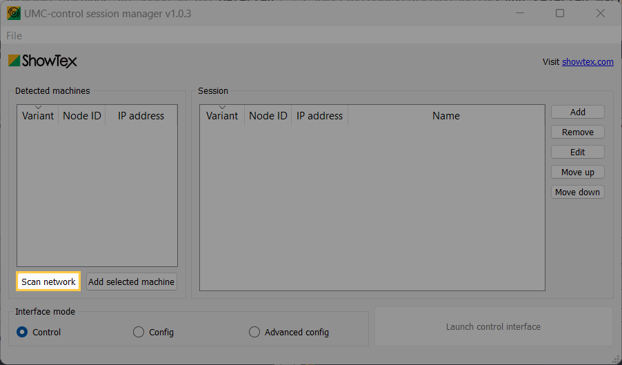
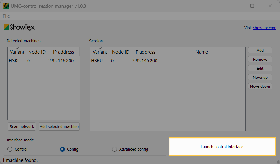
Click on Scan network. Available
machines are added in the
Detected machines list.
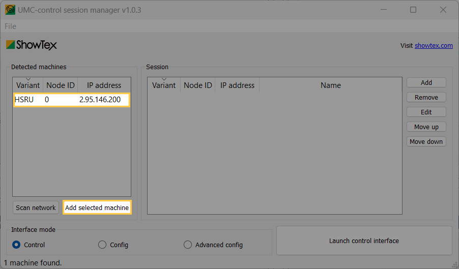
Select the desired machine and click
Add selected machine. It’s also possible
to drag and drop the machine directly in the session list.
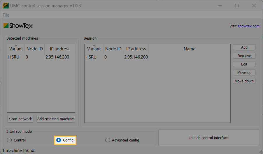
Set the Interface mode to
Config.
Click on
Launch control interface.
When multiple machines are connected on the same network, each machine must have a unique node ID.
The main sections of the control interface are shown in the following image:

The machine section holds every machine added to the machine session list. Each machine widget shows the following parts:
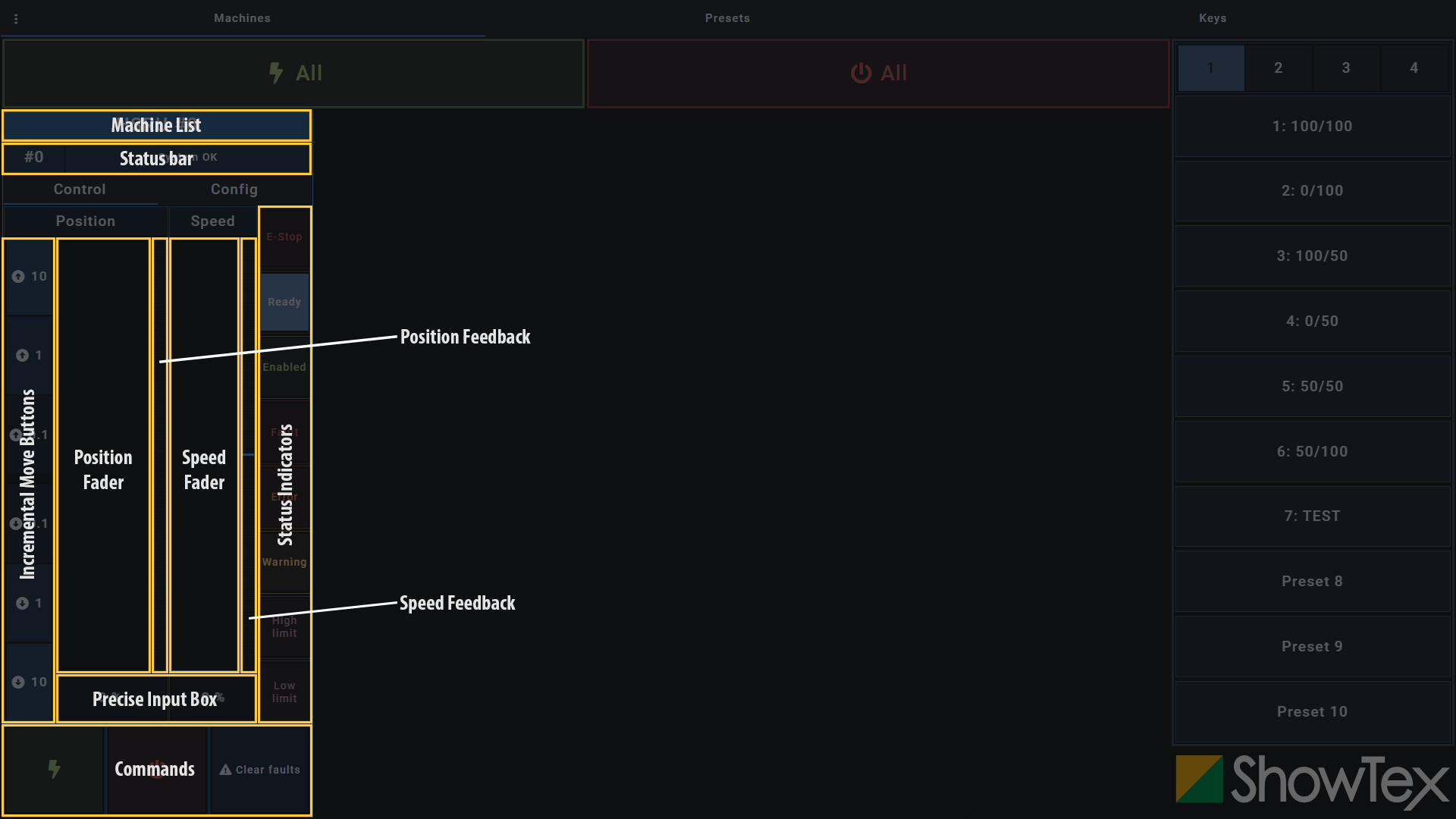
Depending on the control mode selected, the
Config tab will allow you to switch
between controls and configuration views.
In order to get the first machine running, configuration is required for the soft limits. The following steps explain how to configure the soft limits with the UMC, but this can also be done on the embedded LCD screen.
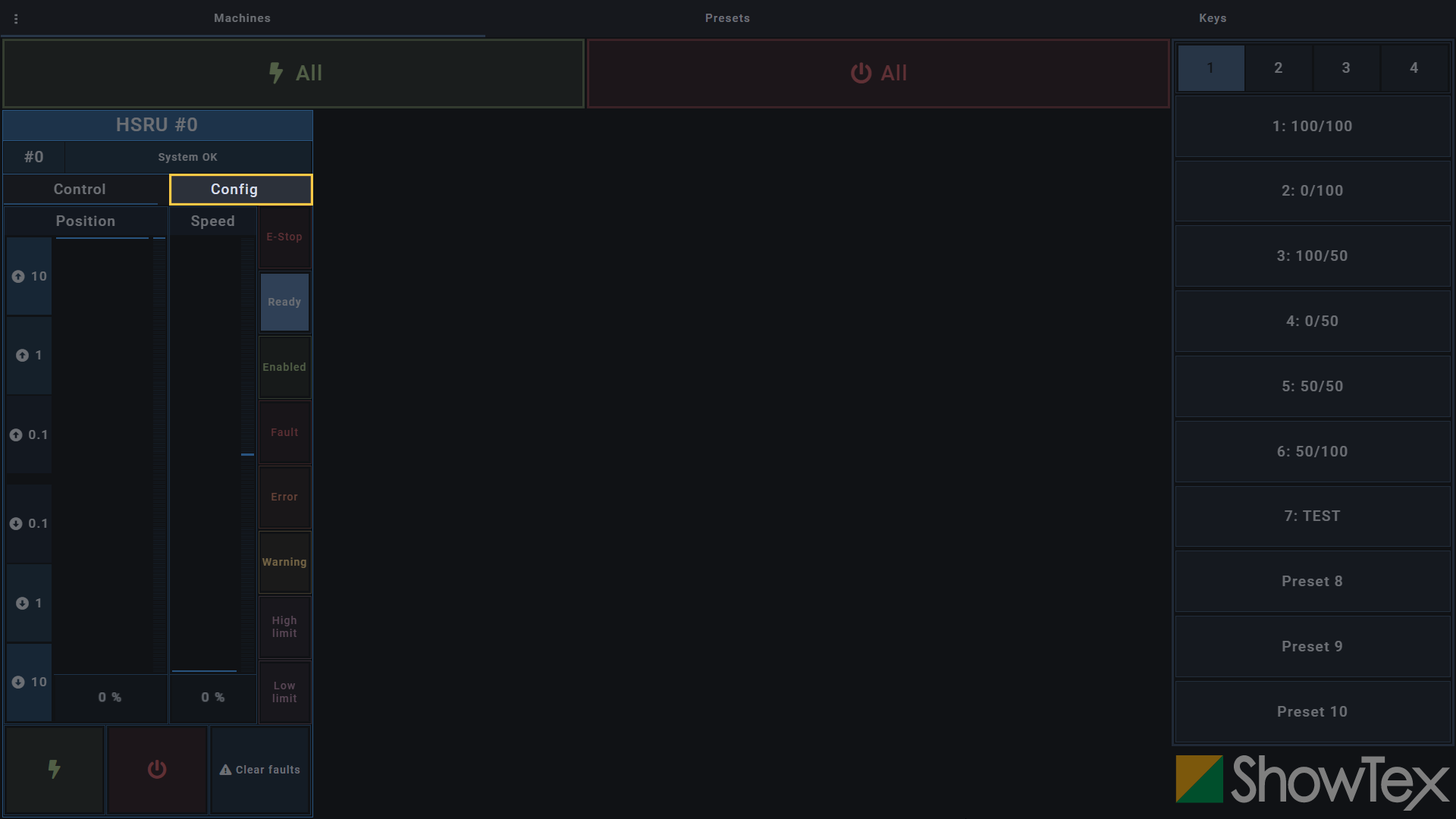
Click on Config to switch to the
Configuration tab.
Click on the dropdown list of the
Drum type section and select the correct
drum type.

Drag the Speed fader up to 10% to
enable a slow reference move.
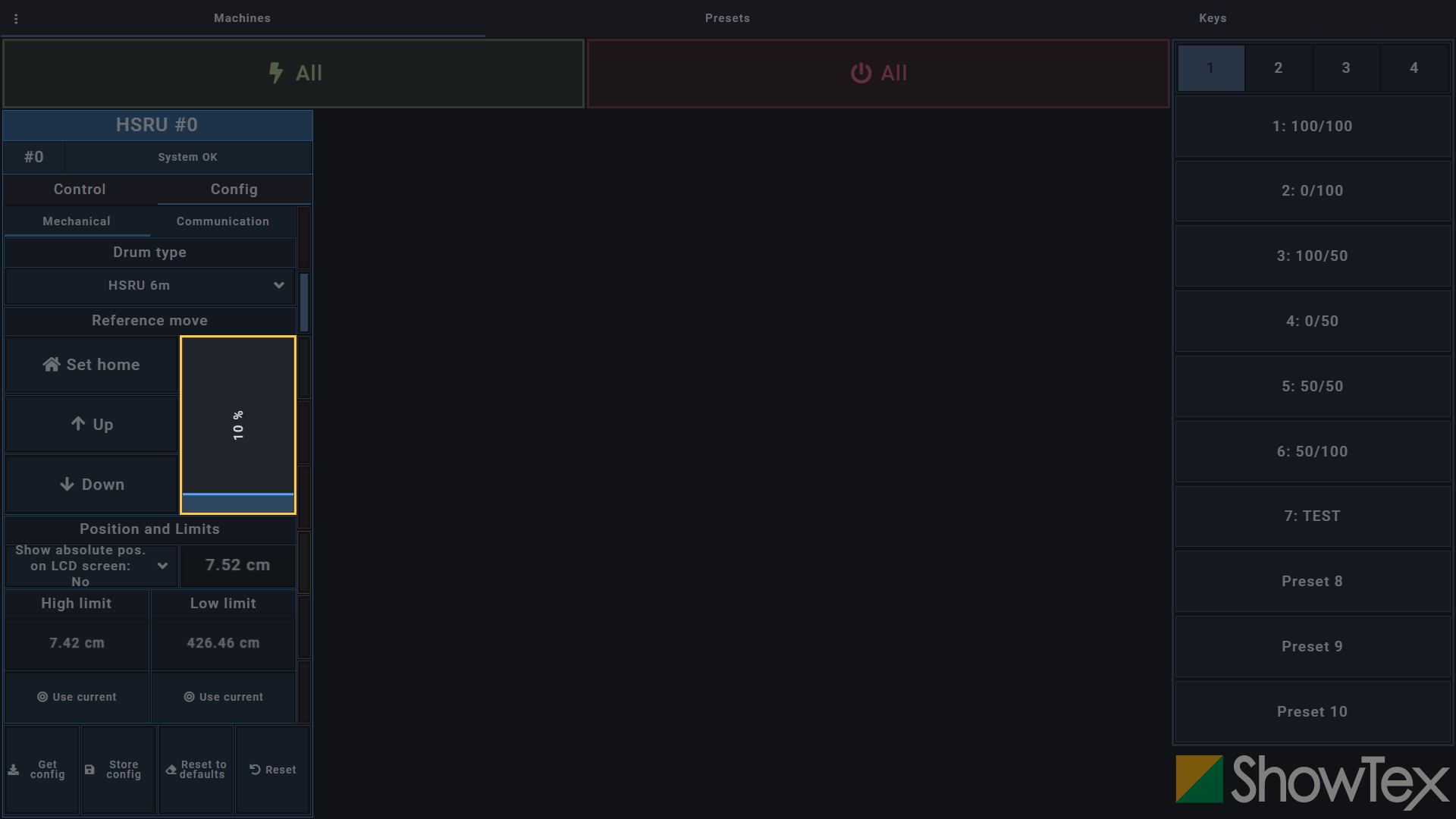
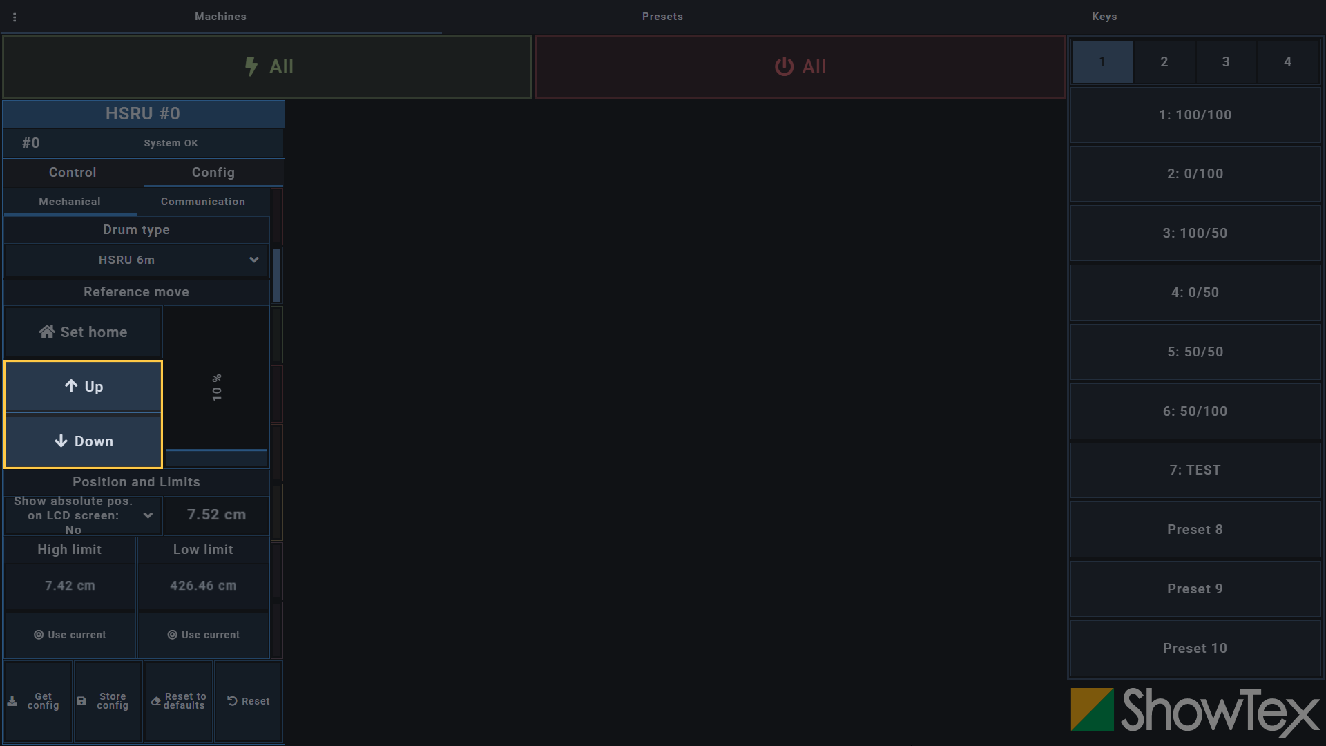
Click and hold the Up or
Down button until you have the desired
retracted position.
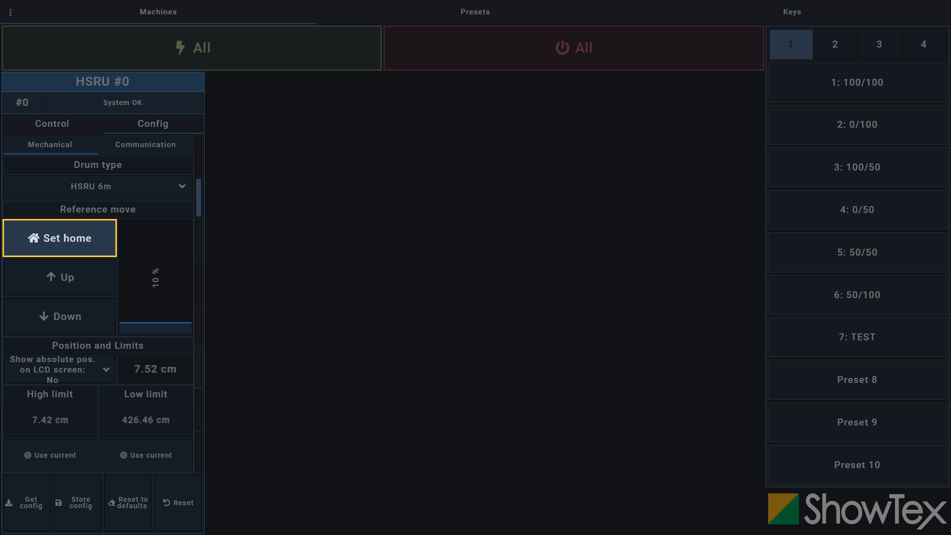
Click on Set home and validate with
the ✔ button to set the current location
as your home.
Click on the @ Use current button
of the High limit section and validate
with the ✔ button to set the current
location as your high limit.

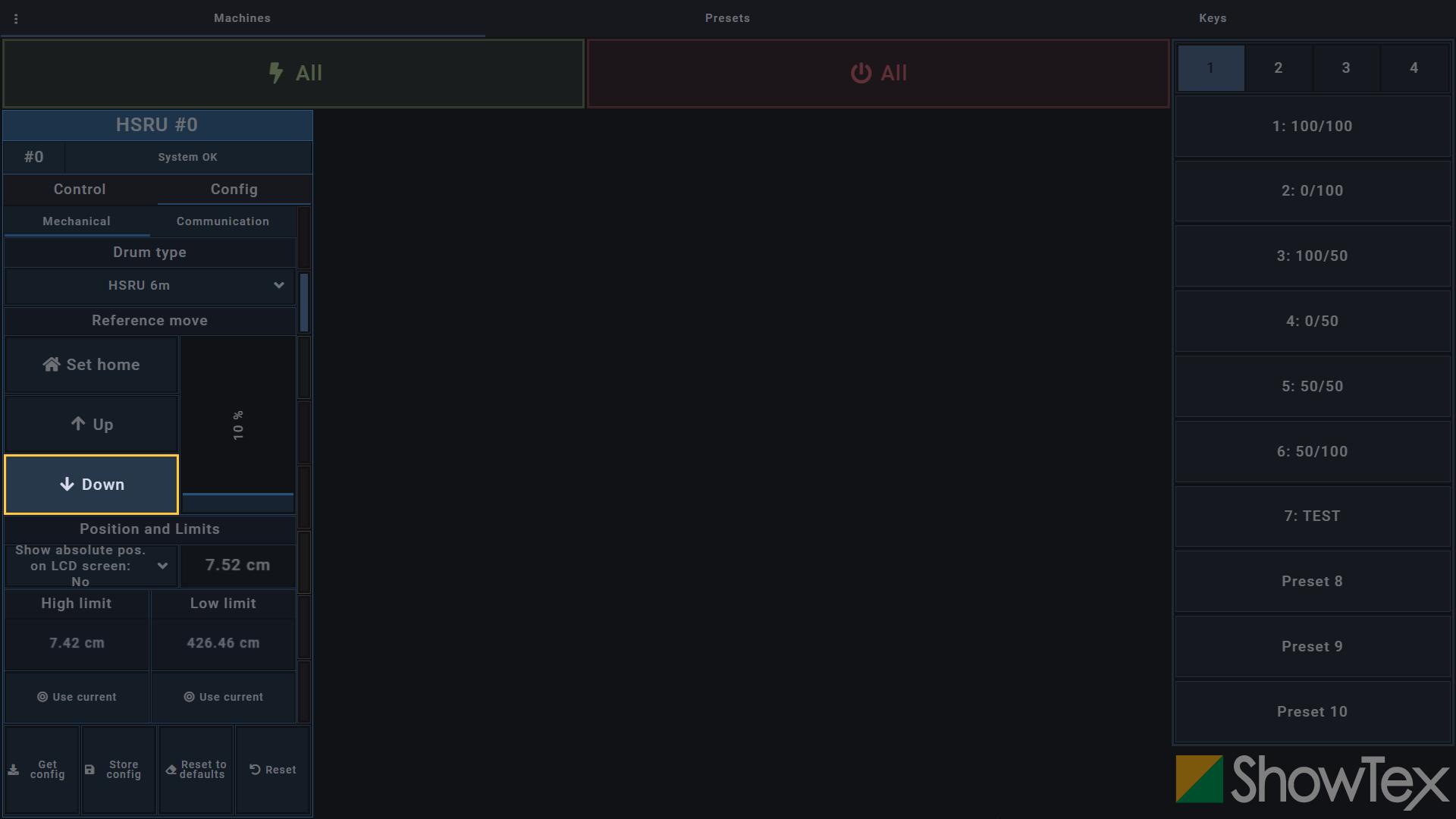
Click and hold the Down button
until you have the desired unrolled position.
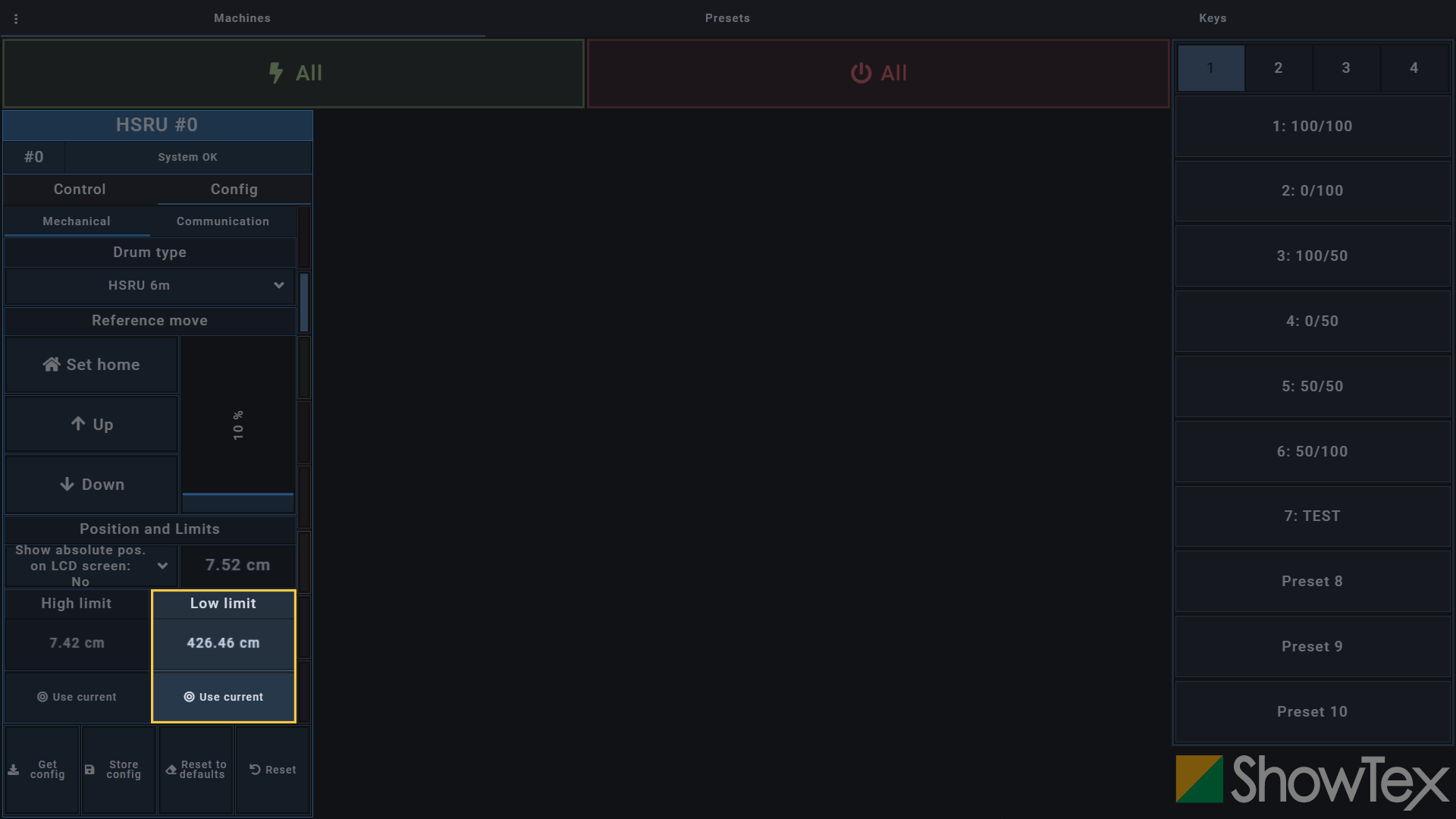
Click on the @ Use current button
of the Low limit section and validate with
the ✔ button to set the current location
as your low limit.
Click on Store config to store your
configured soft limits.
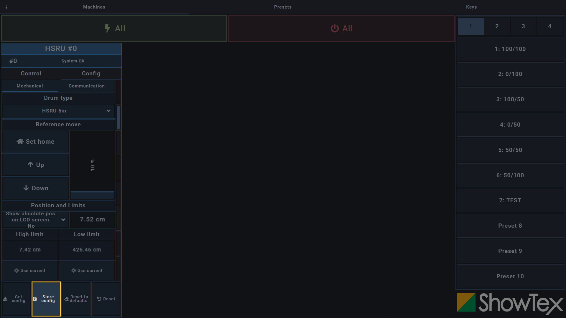
Position the high soft limit under the high hard limit. Position the low soft limit above the low hard limit.
There must be a minimum of 2-3 cm between soft limit stop and hard limit.
To be able to do a first move, go to the
Control tab and click on the
🗲 button to enable the HiSpeed Motor
8000.
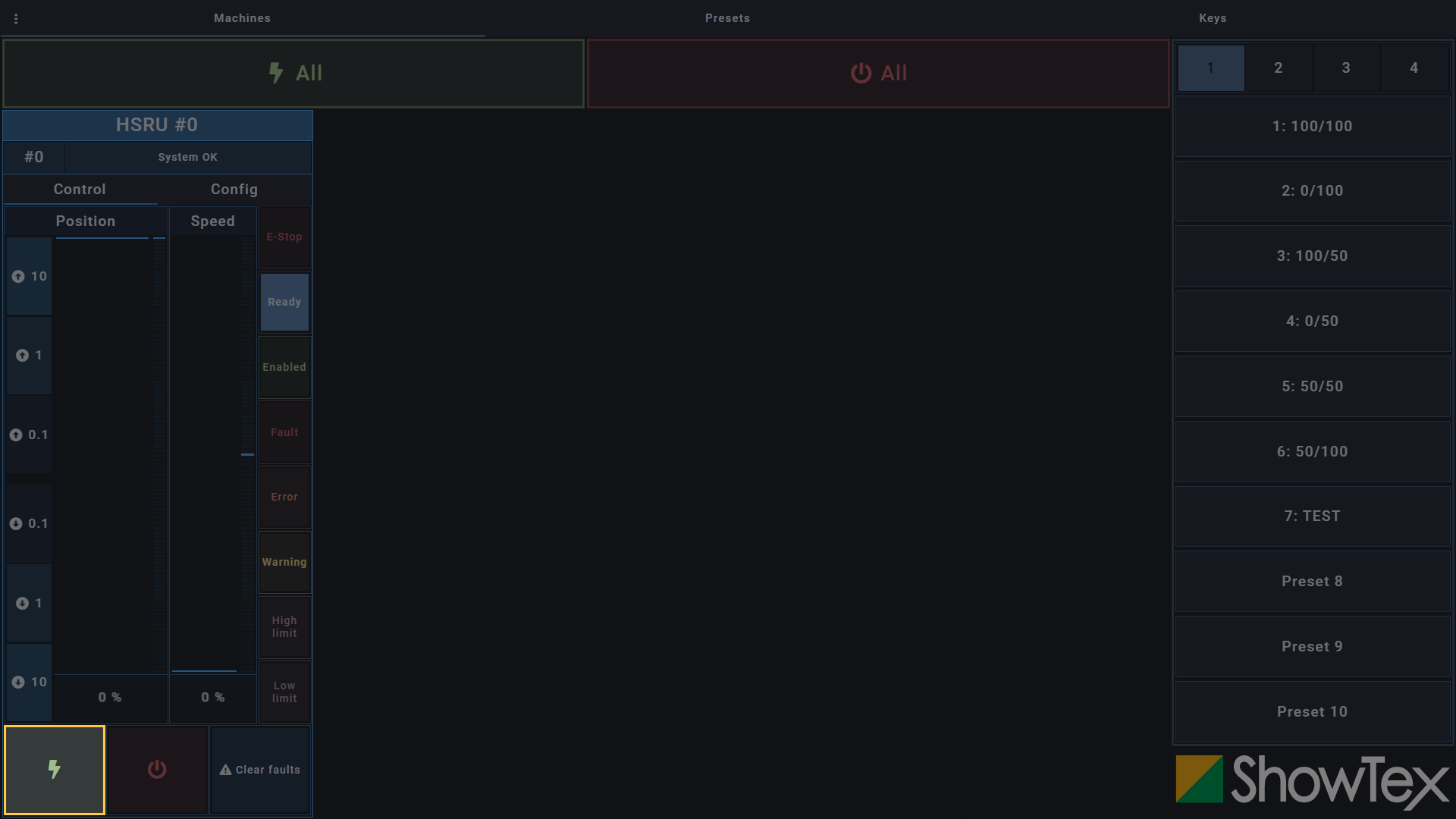
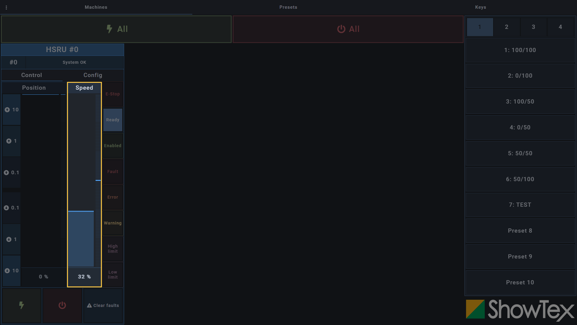
Drag the Speed fader to the desired
speed to enable a move.
Drag the Position fader to perform
a move.
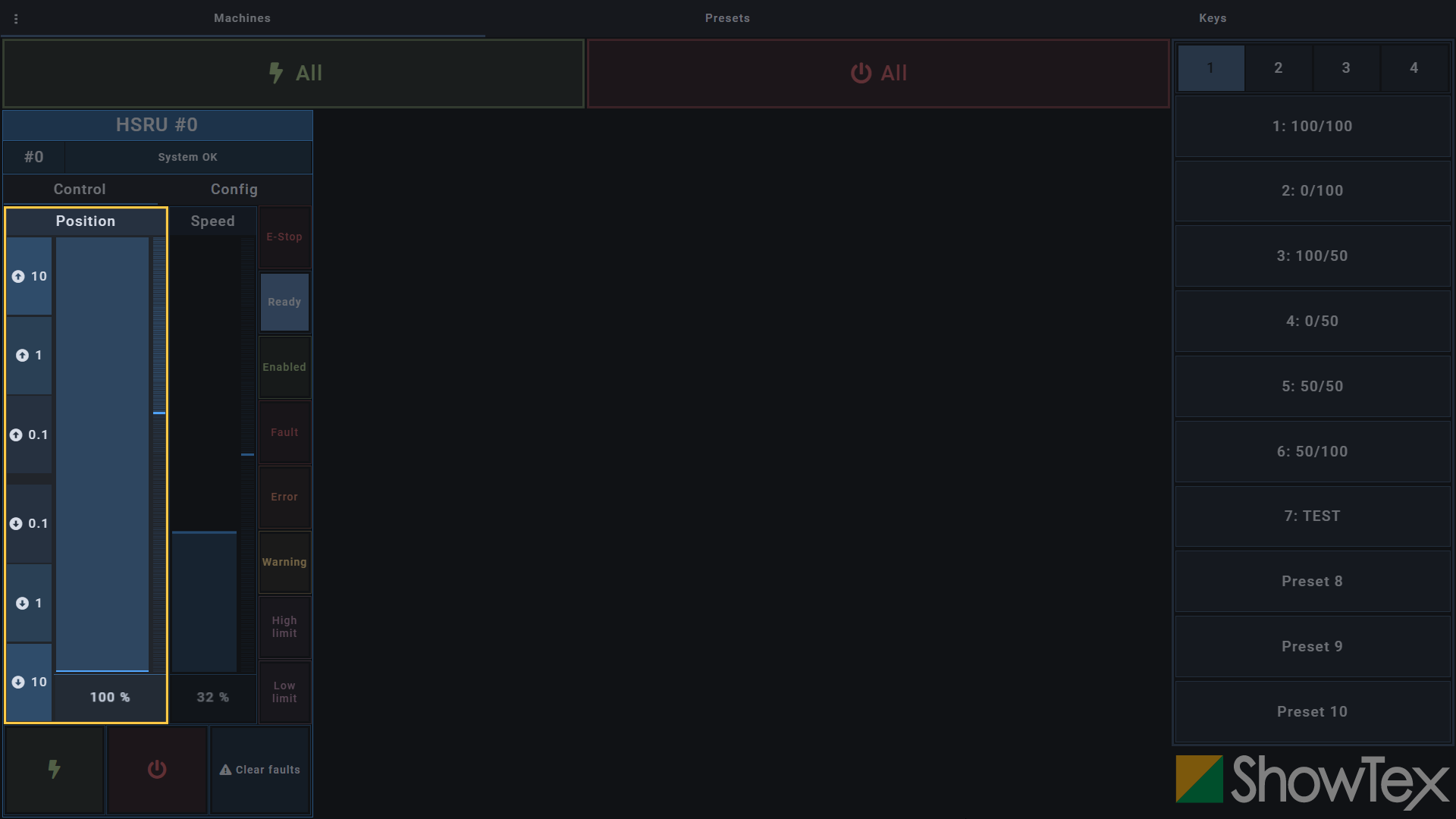
It is advisable to perform the first move at a low speed as a safety measure to ensure that the soft limits are set correctly.
A fault (F) is a condition where something happened and the system
must stop regular functioning. Faults can only be removed by performing
a ⟲ Reset after manual user actions as
something needs to be checked and resolved before resuming regular
functioning.
An error (E) is a condition where the system’s regular functioning is
disrupted. Once the cause of the error is removed, regular functioning
can resume after performing a
⚠ Clear errors.
Go to the Config tab and click on
the ⟲ Reset button for a reset of faults
(F). This step is not needed for errors (E).

Go to the Control tab and click on
the ⚠ Clear errors button to clear errors
(E). The status now should be
System OK.
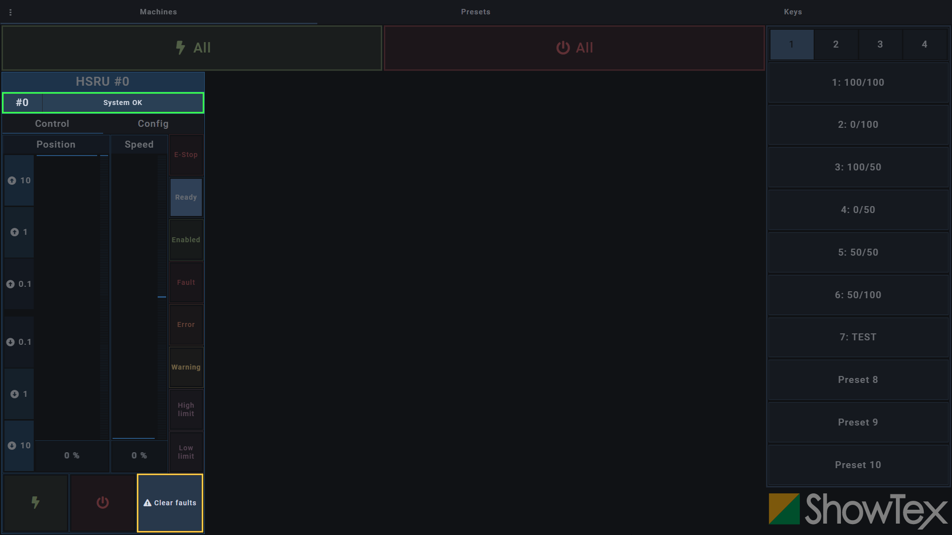
Your HiSpeed Motor 8000 is all set and can now be used at full speed using the Control tab.
For more technical assistance, please contact your local ShowTex
office.
The address and contact information can be found on our website:
www.showtex.com